Cargo Trike Construction Details - Page 3
Page 1 - Rear frame and pivot
Page 2 - Front frame
Page 3 - Completing frame details
Page 4 - Paint, Cargo Box, Lights, and Road Test
Page 5 - Getting the last bits done
Page 6 - Observations, and photos of working and playing.
Conclusion - when it's all said and done...
Update: revised front wheel and brake.
Completing the frame details (and a big "oops!")
Photos 49 through 67.
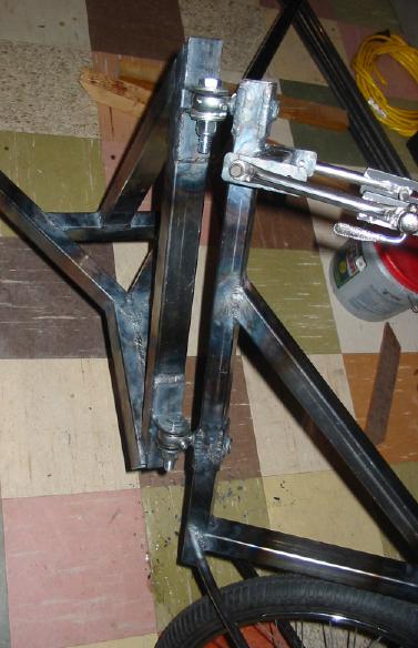
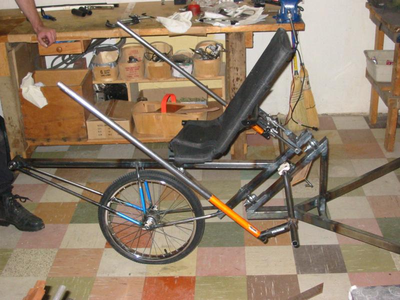
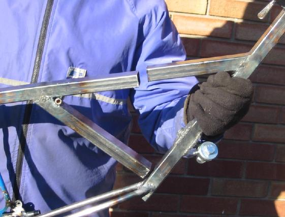
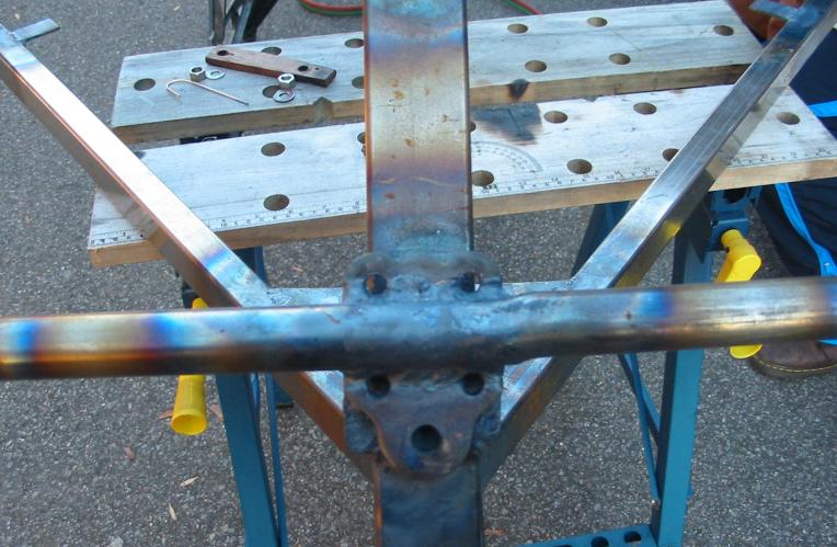
And now we needed handlebars! The bars on this design are fixed to the rear frame, and my original plan was to weld a four-bolt BMX stem and clamp (with stem sawn off) to the rear frame's pivot tube. I cut this down, ground it flat with the table grinder, and also cut a backing plate out of the same metal plate used elsewhere on the trike (inlcuding end-caps for all the frame tubes). But once Juergen welded on the clamp I ran into a problem - as the bolts were threaded through they hit the frame! So they were shortened, but one insisted on stripping when we tried to torque it down, and we couldn't properly re-tap the thread due to the tap not being able to go all the way through becuase of the frame. So I was a tad chagrined (to say the least!) and Juergen suggested we just weld the cross-bar directly to the clamp and leave the top part of it off. I was not happy with the idea of not being able to remove that bar (without a torch) in the future, but at this point we weren't going to un-weld the clamp and start again, so we went ahead with it.
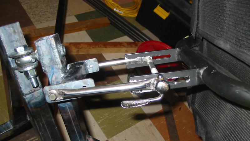
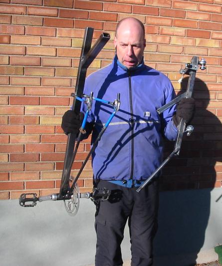
As for the bars that connect to the cross-bar and come up on either side of the seat, we were not yet exactly sure where they should go and how wide they should be. So it was my turn to get clever and use some mtn. bikes stems clamped to the cross-bar, with some scrap tubes attahced to each one and coming up past the seat. They were left extra-long just so we had lots of room to experiment with hand positions. With the front frame parts all coming together it was time to get this beast out on the road for a test ride to se how we were doing! I put on the front wheel, installed the bottom bracket and cranks, and ran the chain.
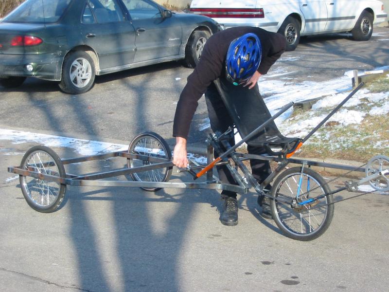
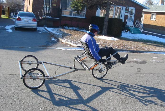
Once I got the two sections of the frame outside I had to connect them together via the pivot point. Lining it all up so that the bolts would run through the holes took a bit of doing on my own (Juergen was busy elsewhere), but I finally got it together and stood back to look at the thing in its unpainted and already getting some light surface rust glory. Juergen showed up, and we got it onto the road and rode it around (in one gear, since the shofter was not yet hooked up). And as we took turns it became quite clear that a mistake had been made!
Remember that negative trail number I talked about before? Well, it manifested itself via the seat being too far forward of the pivot point, as was the front wheel. Consequently the steering was very heavy, and it was quite a workout to bring back to centre. After all the excitement of completing the trike to this point, you can imagine the dissapointment we felt when we realized it wasn't working well. So I disassembled the beast, and back downstairs the parts went as Juergen and I pondered the problem. He asked me "are you sure about the amount of negative trail?" and I said I guess I'd better double-check. We even sent a photo to Dan, and he quickly said yes, you have too much trail and the seat is too far forward. When I got home that evening I searched through my emails and there it was, with the negative trail being specified at 3-4 inches! Arrgghh...
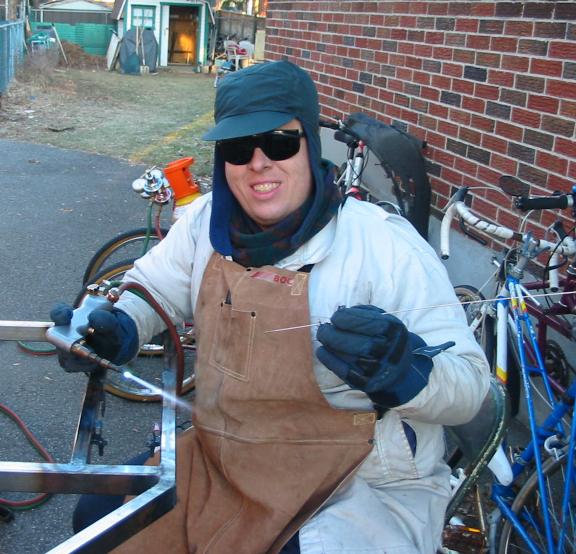
So, once the proper number was at hand we had to figure out how to modify the front end to get this number. It came down to cutting a chunk out of the main tube behind the seat, sawing off the 45 degree tube behind the front wheel and reconnecting it higher up on the pivot tube, and of course lengthening the rearmost wheelstays. Photo #60 below shows my not-so-mock horror at having to cut our nice frame!
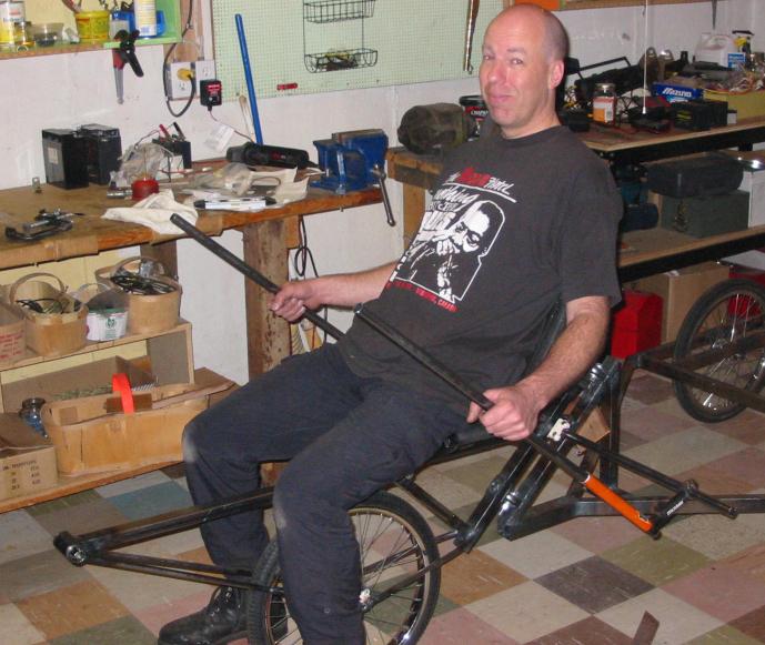
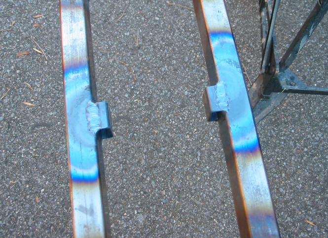
After much grinding and fitting to get the re-cut tube behind the front wheel to fit the pivot tube, thing came back together again fairly quickly. And with the handlebars we decided that it wuld make sende that they be at a 45 deg. angle, just like the pivot. I cut the ends of the handlebars where they would fit the cross-bar so that they would angle outwards a bit. They are made from 7/8" .065 stock, and we were concerned that they might be a bit too flexy. So I angle-cut to shorter tubes of the smaller stock to act as bares where each tube met the cross-bar. The handlebars were left a bit long (but not as long as the temporary ones) until I actually got parts fitted on after painting and knew exaclty where I wanted things to be.
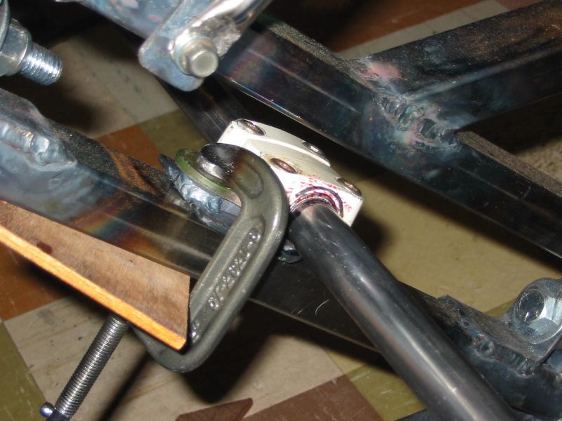
While Juergen was welding this all together he had rear frame leaning to one side. And at one point he called out "hey, it's slipping!", but it wasn't slipping, the heated tube was actually bending! It ended up more than a tad out of whack, but we were able to get back to where it was supposed to be, and the only issue was that the cross-bar had been bent a bit. We decided that bar needed some reinforcing anyhow, and so cleverness struck again when I used the same trick I had used to stiffen a pair of tubes on my - I found a piece of wood dowelling (in this case an old broom handle Juergen had lying around) and tapped it into the cross-bar until it was centred inside that tube. It passed through the bent area without too much effort, and we felt better knowing that area was no longer compromised (if it in fact ever had been).
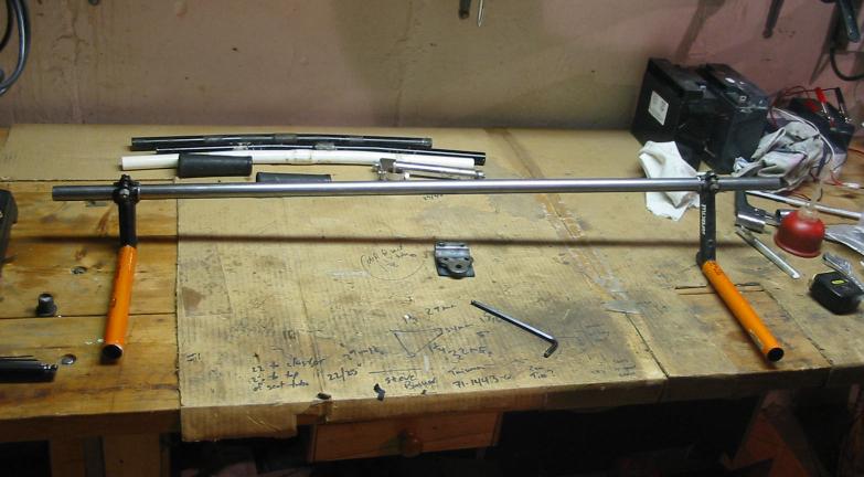
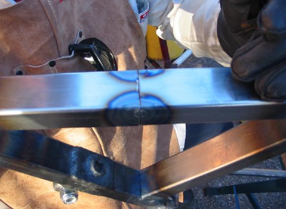
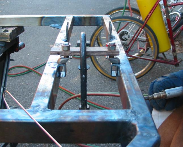
Now we're getting towards the end of all this welding! Next up were the brakes, and we had to mount not only the bosses but some pieces on which to mount the bosses to bring them closer together than the frame tubes would allow. These pieces were just some spare rectangular stock, and they were welded into place, and then the bosses, which had a curve in them to fit to typical round bike tubing, had to have their bottoms ground flat to fit these mounts. Of course the spacing of the bosses was critical to the brakes working properly, so I made up an easy wooden jig to hold each pair the proper distance apart (consisting of a flat piece of wood with a hole towards each end).
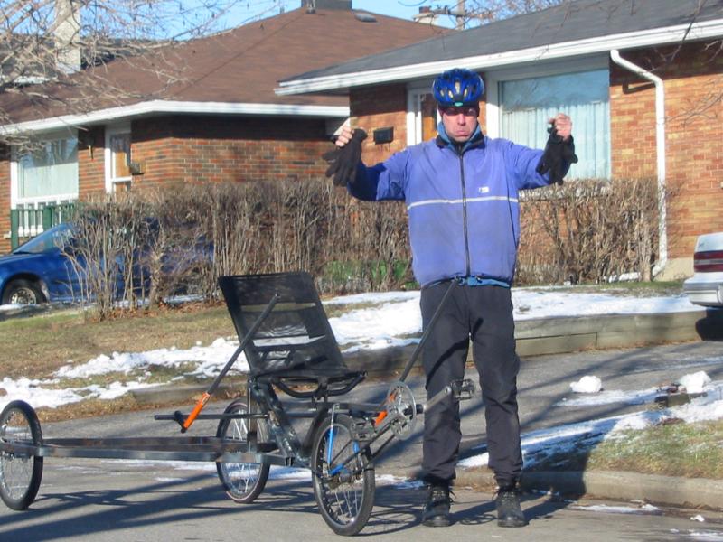
At this point it was about a week before Christmas, and Juergen and I were quite happy that it hadn't snowed all that much yet! It had been getting colder of course, but as long as the ground was more or less bare then it was much easier to work outside in his driveway. After the last photos were taken we still had to braze in the cable stops for the brakes, and that was done a windy and snowy afternoon a few days later. Juergen had to leave the next day for his family holidays, and I had to get my trike out of his basement and over to the next place for its paint job...
|